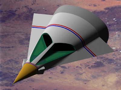
Rendering of 3D Solidworks model by Phil Broad
Sci-Fi & Fantasy Models
International Magazine #38
Article Discussion
by Phil Broad
One thing that every model building fan of Hollywood vehicles wants to do is to build a miniature of their favorite subject, which combines the exterior and interior as shown in the original TV series or film. My favorite subject is the ship from "Planet of the Apes" (original '65 version, not later remakes...) and one issue of the magazine "Science Fiction & Fantasy Models International" featured an article about this very ship, written and illustrated by Jim Key. Jim had taken on the enormous task of trying to, not only illuminate the differences between the exterior miniature Apes Ship and full scale exterior mockup, but also illustrate how the interior might fit into the exterior as well. As many of you probably already know, most Hollywood vehicles feature exteriors which are much smaller than their interiors, making this sort of effort largely impossible (Jim mentions the excellent example of the relationship between the TV series Jupiter II exterior from "lost in Space" and its wildly larger interior). However with the Apes Ship this discrepancy is much less, leaving the fans with a real chance of integrating the two.
The true relationship in the case of the Apes Ship (according to the studio blueprints) is that the exterior mold line used for the mockup is also the interior mold line for the cabin. This means that the actual wall thickness would be in effect, zero. Fortunately this discrepancy is relatively minor when applied to a vehicle that features a straight-cone shape, it simply means that to accommodate the interior, all one needs to do is shift the interior aft (away from the cone apex) to create the required wall thickness. One then integrates the overall design according to which set of features are considered most important to maintain, interior or exterior.
In this case, if one moves the cabin aft it naturally means that the window cutouts in the exterior must also be longer, which then makes the windows themselves somewhat larger. Unless of course one were to shift the exterior window sill upwards to keep the windows the original height, if not the original length. But then, if you shift the sill upwards, the point where the forward edge of the sill meets the fuselage will be farther aft, making the nose cone longer. A different way to do it is by simply creating window frames which also feature a thickness similar to that of the new hull thickness, this then serves to shift the interior cabin aft, preserving the basic exterior "look" of the ship. When studying the studio plans another problem is highlighted by projecting the point where the windows would meet on the centerline (if extended to form a "V"), and then using this as the "point of origin" for the interior cabin, it will be found that these points are not the same distance aft of the cone apex, as seen on the interior and exterior plans.
And so it goes. This gives a very brief idea of the challenges faced by anyone attempting to integrate this ship into one cohesive design. Still, these problems are minor when compared to most other subjects in the science fiction field.
Jim's Plans
It's all too easy to "bash" the efforts of someone else to create plans like these when the person doing the bashing has the actual studio plans in his hands, as in my case and I have no intention of doing that here. I know how much effort is involved in creating such plans, when all one has to work with are photos, because I have done it myself many times. Jim has done a masterful job on a subject which is by no means easy. The exterior was worked up based on the 1/48th scale (1/4 inch to the foot) plans drawn by the studio but the highly complex faceted interior was drawn based on photos alone and this is a real tribute to Jim's powers of observation, logic and design.
The point of this discussion however is to go beyond these drawings by highlighting those details missing and therefore help the model builder to construct a miniature of even greater accuracy. The simple fact is that there are subtleties in this design which are near impossible to pick up via photos and there are also drafting errors on the part of the studio designers which compound the problems (we will get into those later). These issues combine to leave the potential model builder confounded as to why his model doesn't quite "look right".
External Nits to Pick
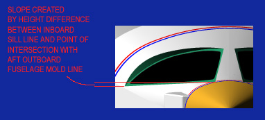
The chief design feature altogether missing from Jim's drawings is the way the two exterior window sills slope downwards, away from the centerline, at about 1.5 degrees or so (I don't know the exact angle). This affects both the exterior and the interior, but it is probably more important to the interior. When constructing a miniature of the exterior, one simply builds the sill in a horizontal line aft, parallel to the centerline, from the point where it intersects the forward fuselage to the point where dimensions tell you it ends, then create a plane by using that line and the outboard point where it should meet the side "chine" or wing (see illustration below).
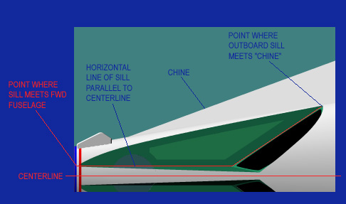
When this is done, you will discover that the horizontal sill slopes downwards slightly (see illustration below). This is correctly reflected in the studio plans, interior set and mockup as well.
Another important variation between what the studio built and the drawings that Jim has prepared are the dimensions given. This is very puzzling since, if Jim had used the actual dimensions given, he would have had more space to fit his interior into because the cabin would have been farther aft in the fuselage and thus would have been wider. The basic dimensions are compared in the illustration below.
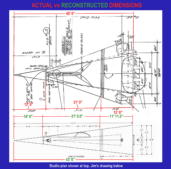
Jim's ship is 43 feet 6 inches long whereas the ship built by the studio was 45 feet in length. This 18 inch difference has more impact on the interior than the exterior but it would seem to me that one would want the largest possible exterior in which to try to fit the interior. In the final analysis, the interior cabin is about 5 feet too long for the exterior anyway, so one will either be forced to lengthen the fuselage or compact the cabin in overall length as Jim has done.
Windows or "View Ports"
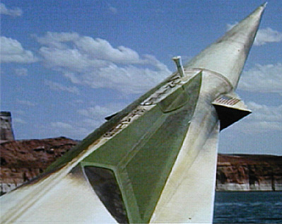
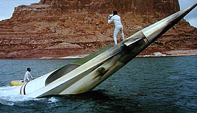
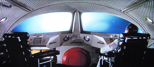
Jim has drawn some interesting details into the windows (or "view ports" as they are called on the studio plans) which, although technically accurate, are inaccurate for a representation of the ship in an undamaged state. It does however accurately reflect the details seen on the miniature (more about the miniature later). The photo below, taken by me at the studio in the early '70s, shows the windows and the specific details we are concerned with here, namely the supporting framing as built into the full scale mockup. This photo and the others like it were taken at a time after the making of "Escape from the Planet of the Apes" and as such, display the severe damage suffered by the mockup when it broke loose from its mooring lines off the California coast and went crashing onto the rocky shore.
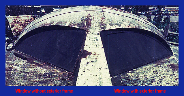
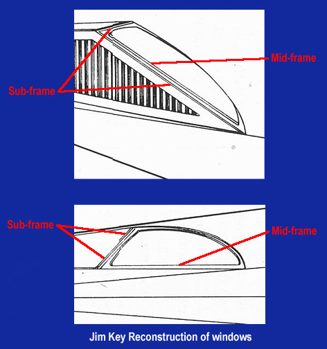
On the right we see the window as it was meant to be filmed, on the left we see an incomplete window, missing its exterior framing. The left window clearly shows us details which Jim has drawn as being on the exterior when in fact, they were not meant to be seen at all. As designed by the studio the full scale mockup was to have double-paned windows, just as a real spacecraft might. This entailed the construction of window framing with provisions for not only keeping the glass panes in the proper location but also keeping them the proper distance apart. So a list of window layers"as built" might be, working from outermost on inward; exterior window frame, exterior glass pane, intra-glass mid-frame and interior glass pane. As seen in the photo below, the exterior glass pane layer also features another sub-frame at the same level which serves to hold the glass "registered" in position.
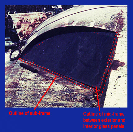
In fact, there were supposed to be rubber seals sandwiched into this assembly as well but in the end they were omitted (more about why the ship was built the way it was and how it was supposed to be used later on in this discussion). My photo below shows the framing details with the glass pane removed.
Observers of the first movie will note that when Charlton Heston gives the order to "blow the hatch" the scene cuts to an exterior view where we are treated to the sight of not only the hatch blowing out but also both sets of windows and the left set of corrugated panels recessed into the widow sills blowing out too. It would be safe to assume that while the exterior glass panels blew out more or less whole, the interior panels were fragmented into tiny bits (the windows were made of heavy tempered glass, not Plexiglas). Please note in the still below that the exterior window frames are clearly visible as still being attached to the glass.
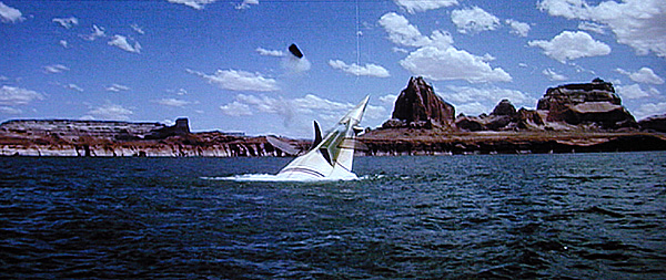
Apparently the studio powder man had not counted on the force of the back-pressure which would be trapped in the mockup when the mortar device went off...
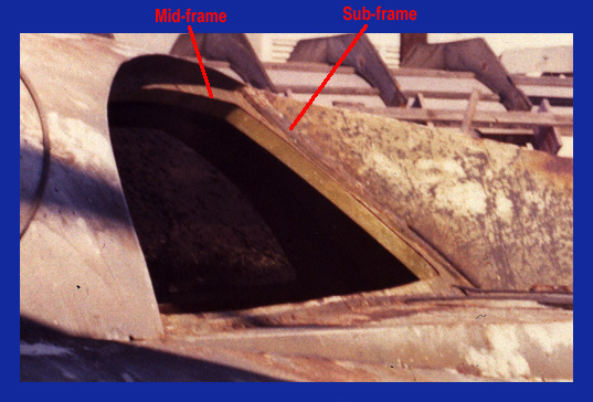
At this point the film makers were faced with an unexpected problem, they now had a ship with no glass in its windows. The interior set were destroyed and the exterior ones were at the bottom of an extremely deep lake. Either they had spare panels on hand (doubtful) or they were forced to stop filming until replacements could be brought in from the studio. So when the glass was finally replaced, it was only placed on the interior side of the frame, thus leaving the mid-frame and sub-frame assemblies exposed and visible to the camera (as seen below).
This would later lead to confusion on the part of the fans as to what the window frame details were supposed to look like, particularly after the film editors chose to place those sequences obviously shot after the hatch had been blown, into the scenes before that event takes place. Below is a chart showing how these internal details are indicated as external in Jim's drawings.
Naturally, one could make the argument that because this is how the ship is seen in the film, this is also how it was meant to be and I would be forced to accept that as reasonable (because it is). However, my personal preference is to err on the side to the plans, rather that the scenes, because this results in a more realistic design. After all, if this ship was real, nobody would equip it with recessed windows, they would be flush-mounted for aerodynamic efficiency. And the flush-mounted "look" seems to be what was originally intended by the designers.
The "Eyebrow"
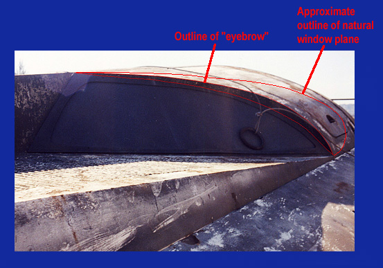
Another detail only just barely shown in the plans from the magazine article but important to the overall look of the windows is the "eyebrow". This device was created from the need of the mockup builders to match or "cope" the aft line of the window cutout to that shown in the original construction plans. This need arose when the window area was first drawn in the small-scale layouts (which are reproduced in the magazine article) and constitutes one of several "drafting errors" found in the studio blueprints. The window cutout outline was shown "as desired" rather than how it would really be if one were to truncate the cone at that position and angle, yet no effort was made by the draftsman to show how this outline would actually be achieved. However, because it was shown with a very specific outline when seen in the plan view drawing, the construction staff in the mill made every effort to match this line, instead of just going with the natural intersection line (see illustration below).
The later and larger-scale plans of the ship compounded this problem further by even including specific details for plotting what would become the upper line of the eyebrow but the "eyebrow" answer itself for achieving this shape is still not shown. We can assume that the draftsman simply left it up to the construction foreman to "figure out". The resulting "eyebrow" shape turned out to be both clever and visually interesting, no thanks to the Art Department...
The Chines or "Wings" & the Subtle Gap
All plans drawn of this ship, whether fan generated or studio originals, incorporate a drafting error regarding the way the chines intersect the cone-shaped hull ("chine" is a naval architecture term which usually refers to the ridges running lengthwise along some hull designs. This term was later adopted by aeronautical engineers as well). In all cases it is drawn as a straight line in both plan and elevation views but anybody who builds a 3D model of it will soon learn that it actually inscribes a slight curve, as seen in the illustration below.

This detail becomes important when trying to locate the outer aft point of the window sill as discussed earlier. The sill height at this point was determined on the mockup according to the blueprints which showed it intersecting at a given point, based on the straight-line plot. However when it was actually built, they discovered that the chine would not be high enough at that point to meet the sill because of its true-shape curved edge. This left the subtle gap which is visible in the photo below.

Exterior Full Scale Mockup Markings
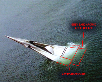
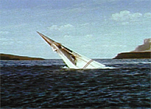
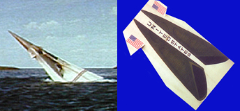
Lastly we come to the ships exterior markings. Unfortunately for the model builder, these were subtlety changed in the various iterations of the ship, for various reasons. The markings seen in the original movie are basically correct as rendered in Jim's drawings with the minor omission of the medium gray band around the aft fuselage (correctly rendered in Greg Jien's restoration of the effects miniature, see photos in miniature section below). Although only just barely visible in a very few scenes (because it was under water), it was there none the less, just as called out on the studio blueprints. Refer to the aerial scenes of the ship in the lake, in these high-angle views it is possible to discern the gray band, seen below water level (as seen below).
Unfortunately the markings had mostly rusted off the mockup when I photographed it and my shot of one of the panels which made up the aft fuselage has been lost. This photo clearly showed the gray band because the panel was not used in "Escape" and therefore never exposed to salt water.
Yes, the nose cone was gold. This is barely discernible in the film because apparently it was finished similar to gold chrome on the full scale mockup and therefore had more reflectivity but less color density. This results in the nose cone appearing very pale, almost white, like the rest of the fuselage.
The studio miniature however seems to have used simple gold paint which has much more color density and therefore appears darker (seen below).
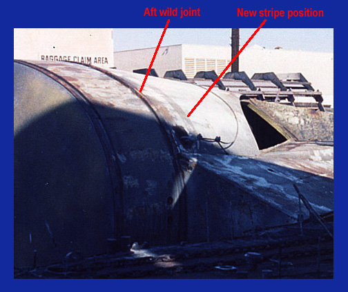
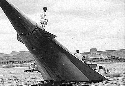
There are transverse blue, white and red stripes (listing fore to aft) at the "wild joints" in the mockup. Wild joints are those places where a movie set or mockup can be disassembled for access or transportation. In the case of the Apes Ship, these joints were marked by the three stripes. The forward set of stripes behind the gold nose cone were each two inches wide, six inches wide in total and the aft set behind the windows were each four inches wide for a total of twelve inches. The location of each wild joint can be determined by the dimensions given in the blueprints and the stripes then located from those joints. The 3/4 inch drawing of the mockup (1/16th scale) shows the forward stripes with their aft edge at the nose cone joint while the aft group of stripes have their forward edge at the aft fuselage joint. In "Escape" however the rear stripes were simply repainted on the hull at the aft edge, just ahead of the new heat shield which replaced the original aft fuselage. This means that the stripes were changed to a location twelve inches forward of their original position, reducing the distance between the aft edge of the window cutout and the front edge of the aft set of stripes. Don't try to measure this distance on photos of the ship sinking in the lake for use on your miniature of the capsule! You will end up with a heat shield which is too far aft by a factor of twelve inches. The stripes are still visible in my photo of the capsule seen below.
The aft section of the original chines still display the original position of the large stripes when they were aft of the rear wild joint (as seen in my photo below).
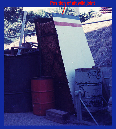
Note the steel internal structure and floatation foam still in place from the filming at Lake Powell. Also note how the chine appears to have been cut at this point, indicating that this unit was originally one piece, not sharing the wild joint of the fuselage at this location.
Exterior Miniature Markings
The markings and details of the effects miniature vary greatly from those of the full scale mockup. I am at a loss to explain this since they both should have been built from the same 1/16th scale plans (the miniature is the same scale as the plans). Therefore I consider the miniature to be inaccurate and this inaccuracy is compounded by the fact that it has been further "restored", therefore making it impossible to say which details are original or which are later embellishments. One thing is certain, the original had neither the closed escape hatch or the glass in the windows (see comparison below).
These were added when it was restored by Greg Jien. Also note the structural inaccuracies of the miniature, chief of these being the way the window sill begins well aft of the forward set of stripes as seen below. The flags seen on the miniature are also too long, the originals being only slightly rectangular in outline.
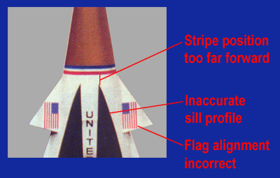
The photo below taken at Lake Powell clearly illustrates the real relationship between the forward stripes, window sill leading edge, canard outline and flag. As shown in the studio plans the flag was to be roughly parallel to the edge of the canard where it joins the fuselage, irrespective of the true centerline of the overall ship.
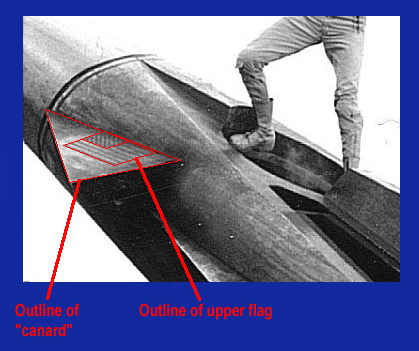
The flags were also applied to both the upper and lower surfaces of the canard with the star field always at the leading edge (two flags therefore are backwards with respect to the intended design). Note the backwards flag on the underside of the canard, visible in the image below.
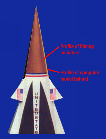
The slightly inaccurate forward profile of the window sill on the miniature must be caused by the cross section of the fuselage itself being wrong at this point (and perhaps throughout the model). The illustration below compares the restored studio miniature to a 3D computer model I built, based on the original blueprints. Note the differences in the window sill leading edge profile. The difference is slight but if you study it, you will see that computer has plotted this outline as curving inward more steeply towards the nose, whereas the studio model shows an almost constant curve. When building a miniature from a cone with an accurate cross section, you achieve an outline such as that rendered by the computer (I know from practical experience).
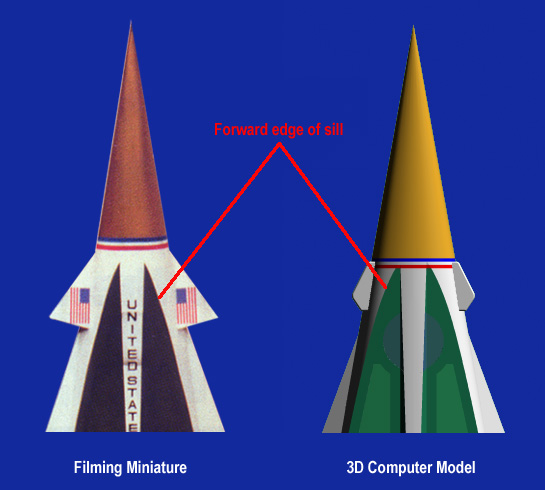
Of further interest are the colors chosen and angle of the cone itself in plan view, as seen here. The almost black shade of green used for the window cutouts on the restored model is far too dark. The actual color was much closer to olive drab or slightly lighter than that (my computer model sports an inaccurate yellow nose cone simply because there was no way for me to render it as gold at that time). The filming miniature also displays a fuselage cone who's angle is too acute in plan view (shown in the overlapping comparison seen below). This and the other details commented on above are indicative of very sloppy model building, hardly up to the standard of other big-budget feature films of the day (such as "Tora, Tora, Tora" who's battleship miniatures were parked right next to the full scale Apes Ship at the studio when I was there).
All these errors combine to create a miniature of little value to those seeking to know the exact details of this ship and it therefore must be left out of any such research, in my opinion.
The Design Implications of What was "Seen" Vs What was "Built"
Nobody knows what the rest of this ship was supposed to look like, not even the Twentieth Century Fox Art Department of 1965. They simply didn't need to or want to. It was enough that the main character arrived in a spaceship and a portion of that ship was seen in the film, the rest was immaterial.
To model builders however, the question of "what the rest of the ship looks like" is central to their efforts to recreate it in miniature. Many model builders are content with building only what was seen or only what was drawn up in studio blueprints, as Jim Key suggests in his drawings. However, this approach may leave the fan slightly empty, with the nagging feeling that there should be more. Why?
The reason is found in the details implied by the features we see in the ship, by the way it flies and most importantly, the mission it was sent to perform.
The single most important detail seen in this ship is a hatch at the rear of the main cabin. This feature states quite clearly that there is a cabin or many cabins beyond that door. Consider also what is NOT seen in the main cabin, details such as a toilet, food preparation area, scientific laboratory, equipment stowage, and possibly even a garage for a surface exploration vehicle. These would all be basic needs to a first-in scout ship on an interstellar mission, particularly one which is most likely one-way! Also, when the ship is preparing to land, we see it climb, bank, roll, dive and pull up again, all characteristics of a vehicle with aerodynamic control surfaces and possibly wings (it might also be a wingless lifting body as suggested in the novelization of "Escape from the Planet of the Apes"). This further indicates the use of landing gear and in fact, as Landon tersely states "We weren't programed to land in the water". These details further serve to put to rest Bill Creber's assertion that the ship might have been a "capsule". Because of what is seen and heard in the film, there must also be room onboard for engines and fuel tanks.
My conclusion is that what hit the water that day so far in the future was a planetary lander at least 150 feet in length (slightly less than the length of an MD-11 jet liner). It had wings, vertical tail surfaces, engines and landing gear. It was also designed to make a landing on an unimproved field, in a totally autonomous mode. Perhaps this was intended to allow the crew to die in their sleep if the mission should fail, even at the final point of landing. The crew are also not "Astronauts" in the sense of being "pilots", as they are usually known today, because of this autonomous flight mode and the total absence of manual flight controls in the cockpit.
The ship would also have a large secondary section, which probably remained in orbit, containing the interstellar drives and fuel to make the long voyage. It is unlikely that the lander which crashes in the lake would contain these drives itself because of the era in which the ship was built (1970s) would not have had sufficiently advanced technology to make them that compact. Much more can be inferred by what is shown, implied and not shown in the film. For further speculation, see my version of the "Mission Plans".
How the Mockup was Built
There remain more than a few mysteries regarding this studio mockup, ones which may never be explained now. Those of you who have seen the documentary about the making of the original movies and the later TV series will undoubtedly have picked up on the comment about the "old plywood spaceship". In fact, Bill Creber the Art Director for this film once commented to a friend of mine about the "plywood spaceship" too, yet the mockup was actually made of steel. Why doesn't he know this?
In Hollywood all mockups and most sets are built of plywood, almost exclusively. One notable exception would be the full scale battleship "Arizona" built largely of aluminum on two ocean going barges for the film "Tora, Tora, Tora". But in most other cases, plywood is the norm. It is strong, cheap, easy to work with and requires no special skills or tools. A simple knowledge of saws, nails and glue is about all you need. However, when the ship from "Planet of the Apes" was designed, it was decided to use sheet steel. I know this because I climbed on it and examined it, inside and out.
Two interesting questions go begging at this point; Why was it made of steel (!) and why doesn't the man who reportedly designed it know this?
Choice of Materials
My only guide in answering this question is the detail found in the blueprints of the ship itself. There is one small sheet which shows how the mockup was to "sink on command" to a point about four feet beneath the surface of the lake. It would then resurface on command as needed. The same drawing shows a figure standing approximately waist deep on the back of the submerged ship, as if the lake were quite shallow at this point. Another drawing shows the highly complex construction of the windows with two layers of glass and multiple layers of rubber seals. The mockup was also intended to contain a mockup of the forward cabin area inside it. From these details it might be assumed that when the ship submerged, the cabin was intended to remain dry? Perhaps they originally intended to simply "open" the hatch instead of the much more dramatic "blowing" of the hatch? It could then be closed before the ship went under, leaving the cabin dry? Perhaps this was meant to explain how the ship could later be "salvaged", either by the apes or by the astronauts themselves? I don't know the answers to these questions but I do know that keeping the cabin dry in real life, even at a depth of only four feet, would have entailed enormous difficulty. The cabin volume of air would exert tremendous buoyancy to the mockup which in turn would require huge ballast tanks and pumps to counter act. This buoyancy would also create enormous stresses within the mockup once submerged, both in bending moment and compression. The logistical support required for this, not to mention the complexity and weight of the final mockup, would undoubtedly be prohibitively expensive to build, transport and set up at Lake Powell.
At some point someone came to their senses and said "we don't need this!". The sinking was filmed with a model and the actors got to climb out of a mockup which not only looked "real", it felt real too!
What the Art Director Knows
I find it very curious that Mr. Creber doesn't know or doesn't remember his "steel spaceship". Yet he did think the subject interesting enough that he kept the filming miniature himself and later used it as decoration in the pond at his home.
If the decision were made to build a studio mockup out of steel, one could well imagine the special meetings which would naturally follow. Meetings to discuss costs, to discuss engineering and who would do it, meetings to discuss transportation and scheduling, and finally, a meeting to cancel the intended use of this overpriced decoration. It would be also be of some interest to the other members of the Hollywood Art Directing community because of its many unusual aspects and would likely be the subject of much discussion. Wouldn't the Art Director involved be more involved on this type of project than most other types? Would it not then form a special memory of a time in his career when the Art Director handled very unusual issues? I would think so but who knows?
Or...
Is it possible instead that Mr. Creber simply didn't have much to do with the issues surrounding the "spaceship" in the first place? We might well imagine that the other many design requirements of this film, such as the Ape City, were considered far more important than the little spaceship which would only occupy a few moments of screen time. This being the case, we could also well imagine that the "spaceship" might then be handed off to an Assistant Art Director (read; "second string") who would then handle it, allowing the more important issues to be dealt with by the "first team". My guess is that, after perhaps throwing out a few sketches, Mr. Creber did no more than "approve" the design work being done by somebody else. However, like so many other things about this ship, we will probably never know for sure one way or the other.